
Appendix B Installation of Remote Termination Panels (RTPs) - Digital Input/Digital Output/Analog Output
194 HC900 Hybrid Controller Installation and User Guide Revision 5
9/03
Digital Input/Digital Output/Analog Output
The DI/DO/AO-RTP is for use with the following modules: See page
• 4-point Analog Output 194
• 16-point Contact Digital Input 195
• 16-point DC Digital Input 197
• 16-point AC Digital Input 198
• 16-point DC Digital Output 200
• 8-point AC Digital Output 201
4 Point Analog Output
Step Action
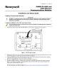
1 ATTENTION: RTP and cables are intended for permanent installation within their own enclosure.
Mount RTP cable assembly to HC900 Controller (Figure 60).
• Remove appropriate key tabs from terminal block to allow mating with the module. See page 64.
• Connect desired cable to AO module at controller. Choose from:
900RTC-L010 Remote Terminal Low Voltage Cable Assembly, 1.0 meters long
900RTC-L025 Remote Terminal Low Voltage Cable Assembly, 2.5 meters long.
900RTC-L050 Remote Terminal Low Voltage Cable Assembly, 5.0 meters long
• Install AO module label onto the module connector cover.
• Connect shield drain wire to the grounding bars at the base of the HC900 rack. All field-wiring
shields must be grounded as described in the shield grounding section (page 60).
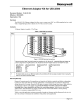
2 Mount RTP to DIN rail.
• Latch to rail. See page 205.
• Connect cable to RTP
3 Set/verify jumper positions as shown for use with an analog output module.
Jumper open
Jumper closed
SW1 is not used. Module RIUP is not affected by using the RTP.
See page 203 for RTP internal schematic.


 England
  Deutschland
  France
  Italia
  Polska
  United Kingdom
  Россия
  Nederland
  España
  Magyarország
  Sverige
  România
  Portugal
  Colombia
  Suomi
Suomi  New Zealand
  Česká republika
  Türkiye
  Danmark
  日本
日本